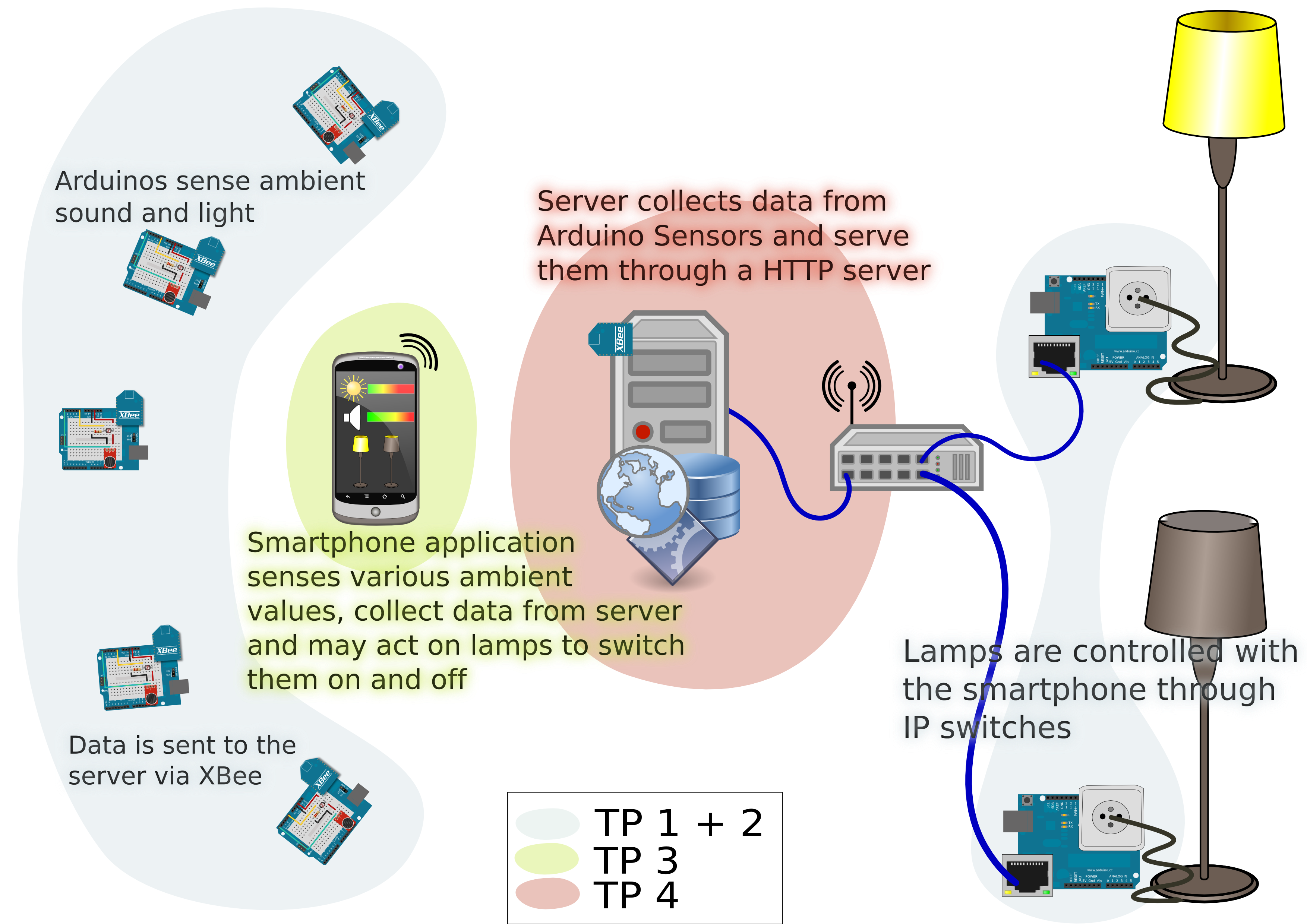
The goal of these lab sessions is to build a complete system where:
sensors collect data about ambient light and sound
a context server asks sensors to send the collected data and store them in a database
actuators are set on floor lamps to switch them on and off through an IP network
an android device asks the server for values from the sensors and take decisions on various things according to these values. It is also able to switch floor lamps on and off.
The schema below describes the system.
Overview of the complete system along with related lab sessions.
During this first lab session, you will learn how to build the sensors and the actuators. But you won't do both. Some groups will work on sensors and some groups will work on actuators.
Both parts involve some electronic devices, but the wirings hare quite easy to do. Your job is to write the software to drive all these electronic devices. Of course, the programming platform is Arduino as seen during the course presentation.
Sensing light and sound, serving data through serial link
You must build an electronic circuit that matches the schema below.
Electronic circuit for sensors.
A wiring example of this electronic circuit is shown on the picture below. Your breadboard should look like this schema. Please double check the wirings before plugging your Arduino board to your computer.
Breadboard example for sensors circuit.
If you do not understand whats going on with these schemas, don't panic! You should only keep in mind that this circuit is able to sense sound and light with the help of the Arduino board. However, if you want to know more on how it works, you may read some explanations on wiring and reading values from an analog sensor.
To help you begin with your programming work, you may create a new Arduino sketch named sound_and_light_sensors, then download the file sound_and_light_sensors.ino and copy it into the sketch folder (usually Documents/Arduino/sound_and_light_sensors/). This is a skeleton of code that gives you the basics to bootstrap your project.
Don't try to do everything in a single shot. First try to make the sensors work with analogRead() and convert the values to something useful if needed (values between 0 and 1 for example).
Then you should work on the serial server and make it answer to the following commands:
LGET to get the value of ambient light;
SGET to get a value for the ambient sound level.
You should take a look at the example sketch File->Examples->Communications->SerialEvent of the Arduino IDE.
As these modules are to be used with ZigBee shields, we won't be able to debug things by printing on the serial port. That's why we have two LEDs in this project. You will have to make them light on and off or even blink depending on what's happening on the serial server. Rules follow. You may read more on wiring LEDs to understand the way they are wired and how they must be controlled.
The two LEDs present on the breadboard must provide the user with a visual feedback about serial communication:
Green LED blinks on serial input;
If a request is sent to the Arduino and is valid, the green LED will be lit for 0.5s;
If a request is sent to the Arduino and is invalid, the yellow LED will be lit for 1s;
When a answer is sent, green LED will blink fast for 1s.
In order to test your serial server, you should use the serial monitor of the Arduino IDE. Do not forget to set Line Ending to New Line unless no new line is sent and your server will wait forever.
That's all, you're done with your work! You should now show it to your teacher if not done yet...
Controlling a switch through an IP network
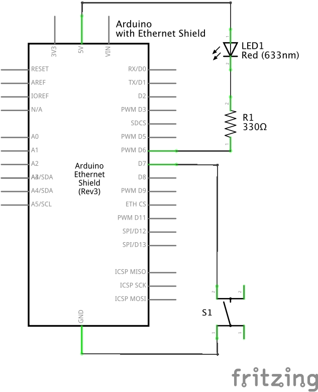
You must build an electronic circuit that matches the schema below.
Electronic circuit for the IP switch.
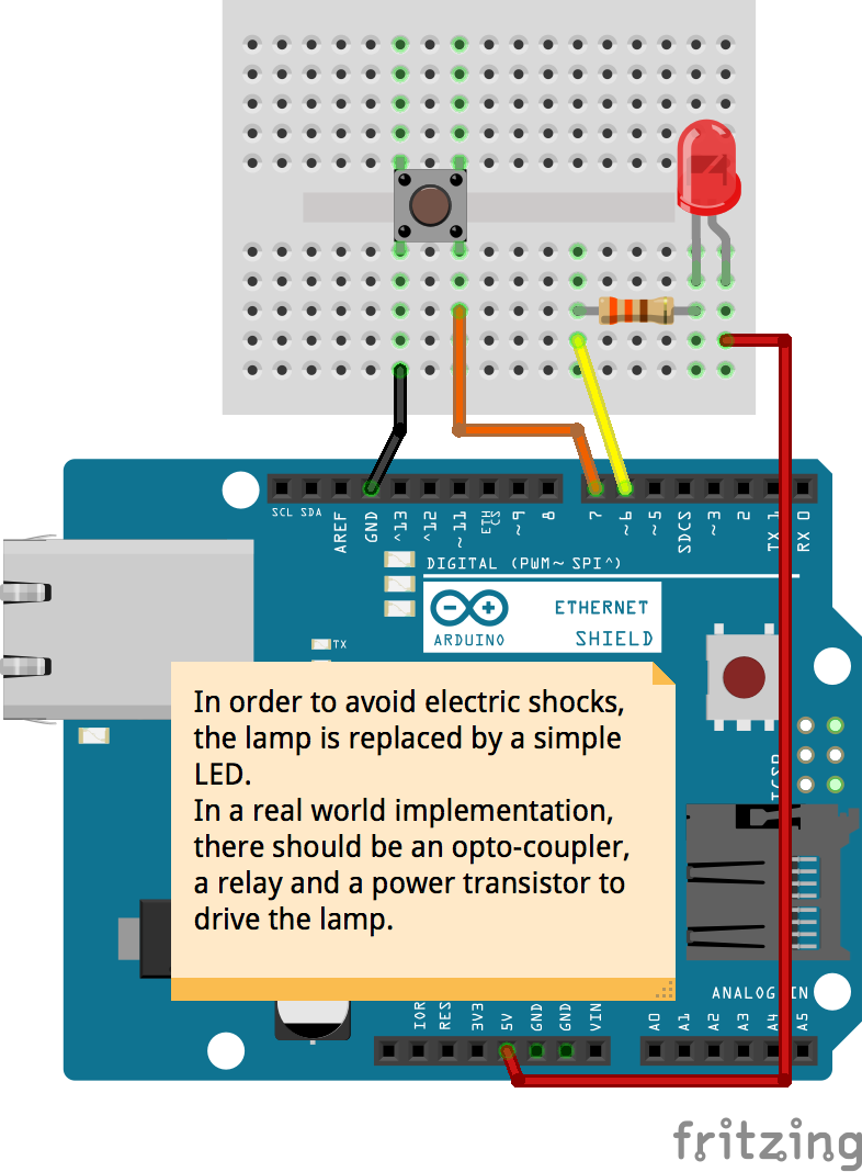
A wiring example of this electronic circuit is shown by the picture below. Your breadboard should look like this schema. Please double check the wirings before plugging your Arduino board to your computer.
Only the Ethernet shield is shown on this schema. Actually, you have to plug it on top of the Arduino module. Please be cautious not to bend the pins as they are fragile and may break easily.
To help you begin with your programming work, you may create a new Arduino sketch named ip_switch, then download the file ip_switch.ino and copy it into the sketch folder (usually Documents/Arduino/ip_switch/). This is a skeleton of code that gives you the basics to begin your project.
Don't try to do everything in a single shot. First try to read switch status and light LED on and off depending on the switch position.
Then, look at the example sketch Files->Examples->Ethernet->WebServer in the Arduino IDE and create your own web server. It must answers to GET HTTP commands with URLs of the form: http://the.arduino.ip.address/COMMAND, where COMMAND is one of:
ON, to switch light on
OFF, to switch light off
STATUS, to get status of light (ON or OFF)
Answer sent by your server must be valid HTML with a valid HTTP header so every browser may understand it well. Browsers on mobile devices seem to be picky about HTTP headers.
The IP stack on the Ethernet shield must be initialized with a valid IP address. We will use network 192.168.0.0. You will choose addresses from 10 to 15, being sure not to take the same address as your neighbours!
The MAC Layer of the Physical Layer of this shield must also be initialized, but with a valid Hardware address this time. Fortunately, you do not have to create one as there's one already written on the back of the shield. Using it ensures that you have an unique hardware address (also known as MAC address) and that there won't be any problems communicating on the Ethernet link.
To test your web server as well as your entire project, you will have to plug one end of en Ethernet cable to the Ethernet shield and the other end to the hub present in the classroom. You can then connect a mobile device via Wi-Fi using the correct network (ask your teacher for the network SSID if he hasn't already told you) and send request to your Arduino using its IP address. Of course, you can also test your friends' projects!
That's all, you're done with your work! Do not forget to show your code to your teacher if not done yet.
About the switch
The switch you use is in fact a push-button. However, you must write your program so that this push-button acts as a switch. Have a look at the time diagram below. You may notice that it is not a state of the switch you look after, but a change of state, a front. In the diagram below, the LED state changes when a rising front is found on the switch (the switch is released). You must program your Arduino to read the switch this way.
Time diagrams for push-button and LED.
Whichever way your push-button is acting, it will always bounce. That's often what happens when mechanical parts are involved. These bounces will produce false data when reading from the Arduino. You must avoid them to prevent you light from flickering unexpectedly. You may read how to debounce a switch to learn how to prevent it.